FIBOT Docs
Manual book for Fibot
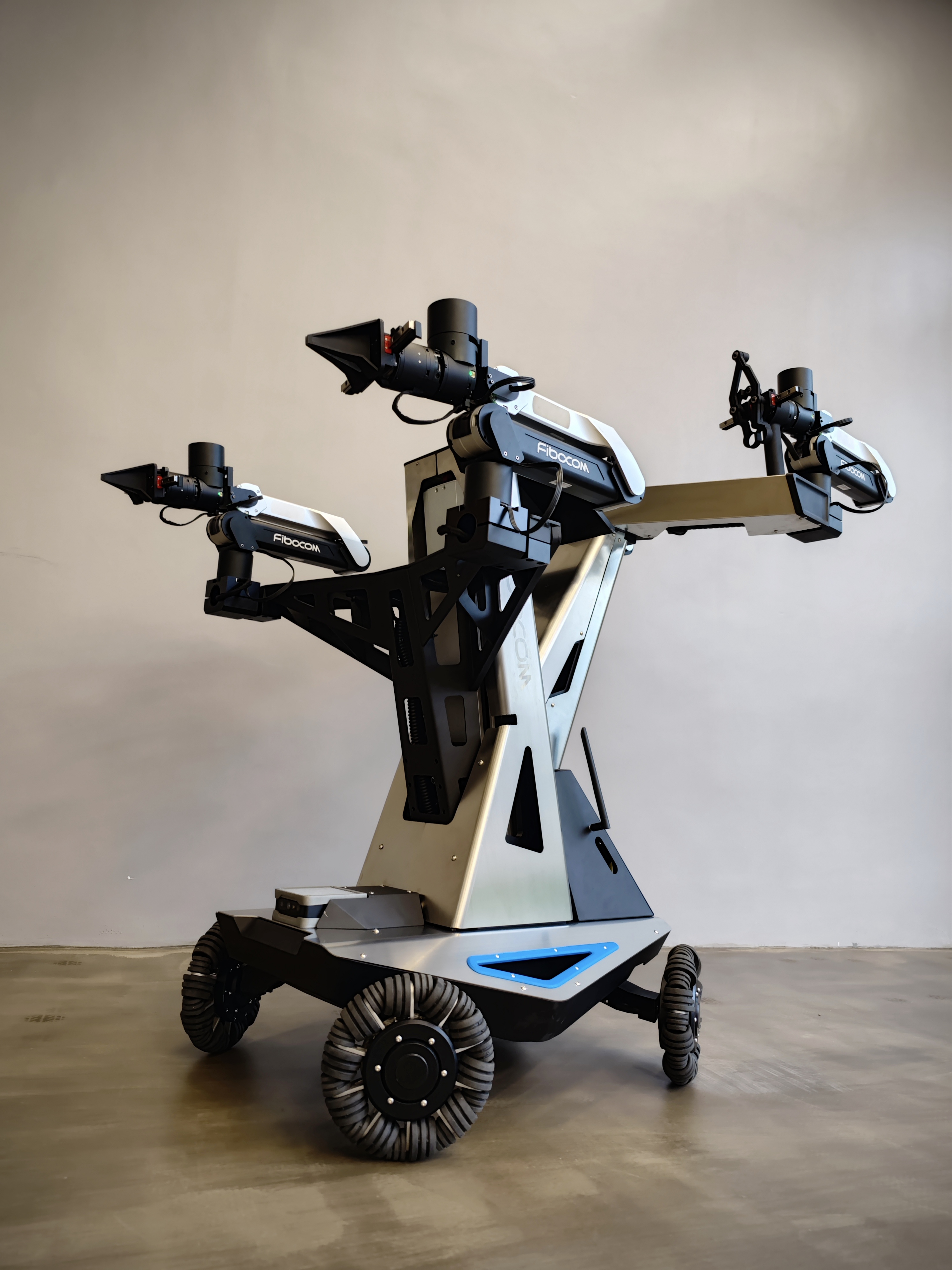
FIBOT 4X Manual
PoweringUp
Before Powering Up
- ⚠️⚠️⚠️ Make sure that the arms are in a poper location before powering up. Upon boot up, the arms will try to go back to their initial position, if not in poper location it could hurt you.
PowerUp
- Press the power button, and the robot will boot automatically
Try Out
When the bot successfully boots, the images from the RGBD camera will shou up on the screen. And all leds on the arm will turn green.
PLEASE make sure you WAIT for the leds to turn green. Do NOT move the arms before it's ready or people might get hurt.
Opreate the arm
The robot is equipped with a mechanical arm base, allowing users to conveniently place the mechanical arm on the base to prevent it from moving randomly.
Move the robot around
To move the robot around, you don't have to use a remote(You can if you want though). Just grab the hand rail, and push/pull the robot anywhere you want. In free movement mode, you can move the robot forward and backward, left and right, and rotate it freely.

Use the arm lifter
We have designed a lifting platform for the mechanical arm to expand its workspace. You can use the blue rotary button on the handle to control the height of the lifting platform.
The lifting platform dramatically increased the workspace of the mechanical arm, enabling vertical opreation.


Developing
Where is the code
Currently, the PC has a debian installed. ROS is running inside docker images.
Using docker has obvious advantanges
- Easily roll back to a known good state
- Run linux on latest hardware without drive issues(Old hardware + New Linux or New hardware + Old Linux tend to always have driver issue.)
- Mixing different ROS versions without any problem.
Curretly, this device has 3 docker containers on it
- arm container
- RGBD camera
- chasis control node
The docker file and contents inside are just laying on the disk. It's up to you to decide to keep using docker or not. Just read the docker file, it is reall easy to understand what's going on. If you somehow want to install a Ubuntu 20.04 (ROS2 is impossible because the Ark5 Arm does not support ROS2 yet) and run ROS bare metal, read the following instructions.
Getting HEXMOVE ROS SDK
Please visit https://docs.hexmove.cn/books/public-hexmove-docs/chapter/ros-sdk-user-guide for instructions on how to download and use the HEXMOVE ROS SDK.
Work Gracefully with the robot
We have a small platform so you could place keyboard/laptop on it, and dev like a pro.


FIBOT-4A Manual v1.0
Prepare Hardware
1. Handle Button Function Description
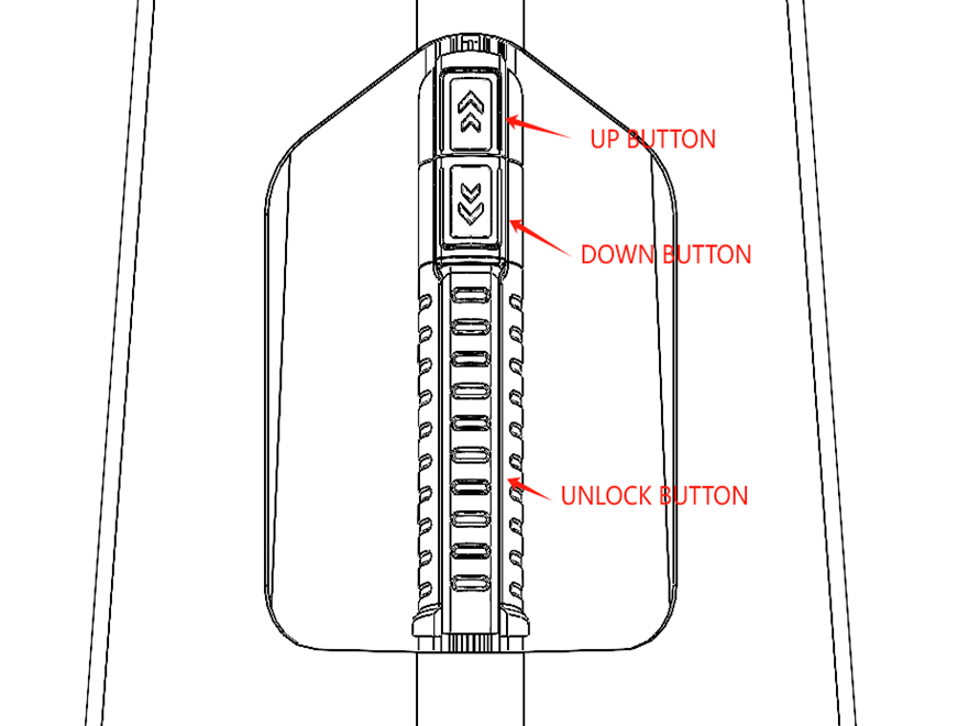
1.1 Tower handle
At the back of the tower, there is a handle button area, as shown in the figure below.
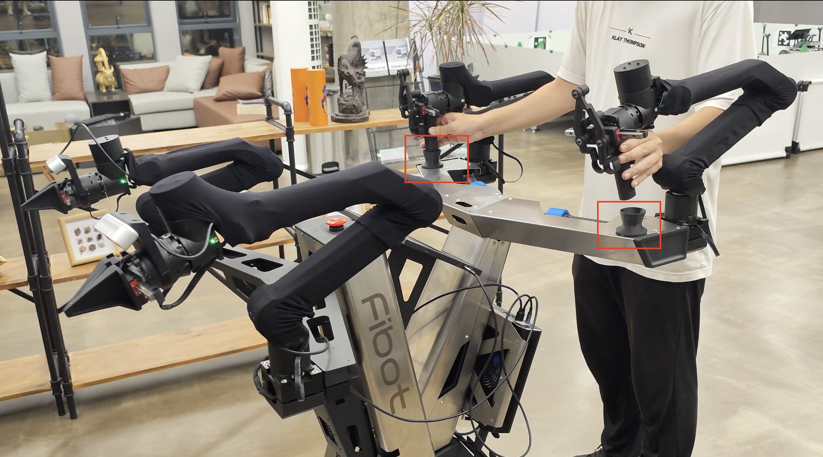
1.2 Rear platform handle
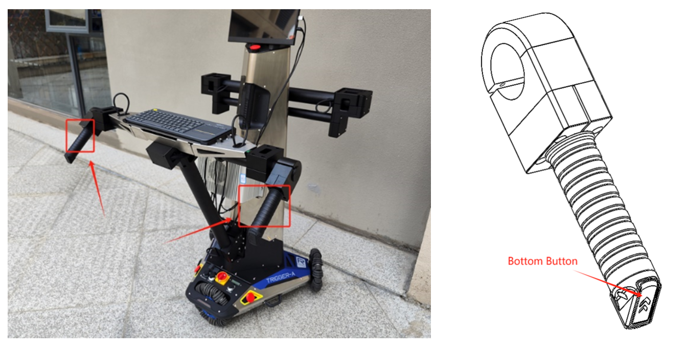
As shown in the left image above, the rear platform has two handles, each with two buttons. When the buttons on the back part of the handle, outlined in the red box in the left image, are pressed simultaneously, the chassis parking lock mode is released, allowing the chassis to be freely moved. In the right image above, there is another button below the handle, which is used to control the lifting. Pressing it will control the ascent or descent of the robotic arm platform in front
The two handles are not suitable for lifting the robot.
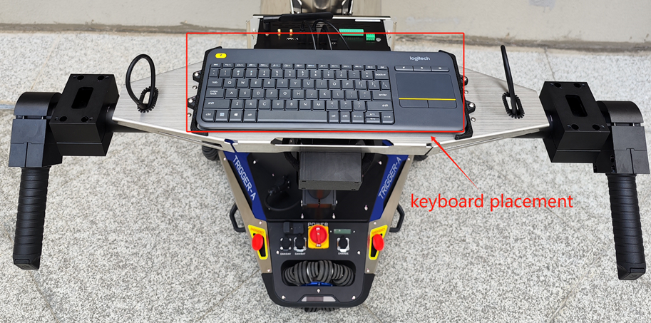
2. Rear Platform Keyboard Placement Instructions
There are two black plastic components on the rear platform, designed to position the accompanying Logitech keyboard and prevent it from moving, as shown in the image.
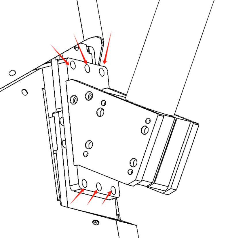
3. Rear Platform Disassembly Instructions
Considering that the robot may need to operate without the rear platform, the rear platform is designed to be removable. The specific removal method is shown in the image: unscrew the six screws indicated by the red arrows.
4. Front Paltform Installation Instructions
First of all, when installing the front platform, note that the pink arrow with the number 5 should face outward, consistent with the position in the image below.
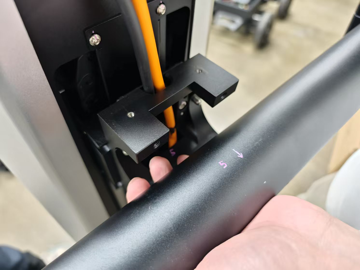
In the second step, the parts fixing the aluminum tube are fixed by screws, as shown in the following figure.

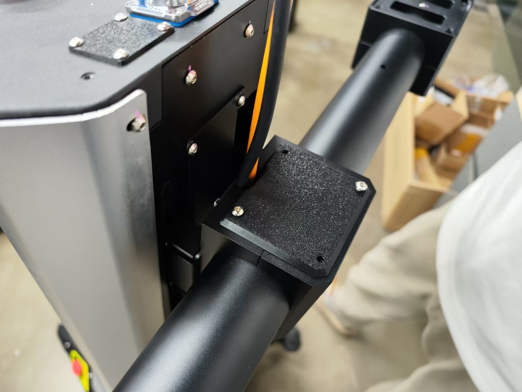
Note that if installed according to the first step, the mounting plane of the mechanical arm is horizontal at this time, as shown in the following figure.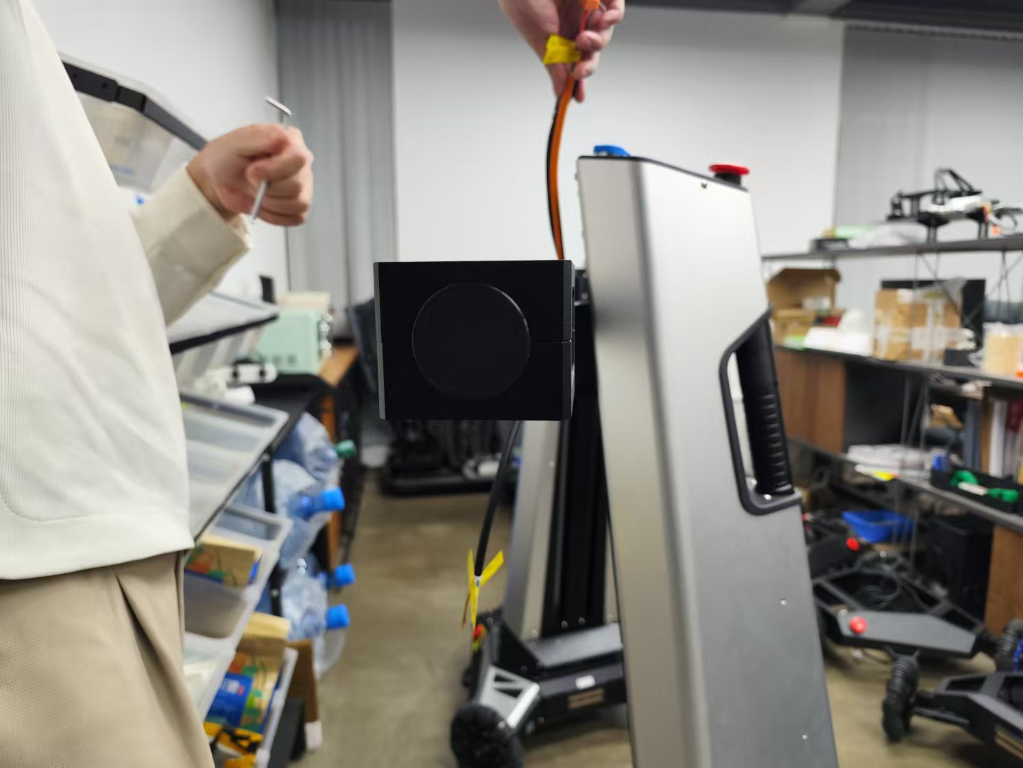
In the last step, the plastic parts of the cover plate are installed on the aluminum workpiece in the middle of the platform by screws, as shown in the following figure.
5. Wiring Instructions
5.1 Rear Platform Main Power Wiring

The rear platform has a black 4-pin aviation connector, which should be plugged into the socket located at the base of the tower, as shown in the image.
5.2 Three USB ports on the top of the tower

There are three USB 3.0 ports at the top of the tower, as shown in the left image, reserved for connecting cameras. The cables for these ports have already been extended to the base of the tower. You will need to connect the other end of these three USB ports to the industrial computer, as shown in the right image.
5.3 Industrial Computer Power Wiring
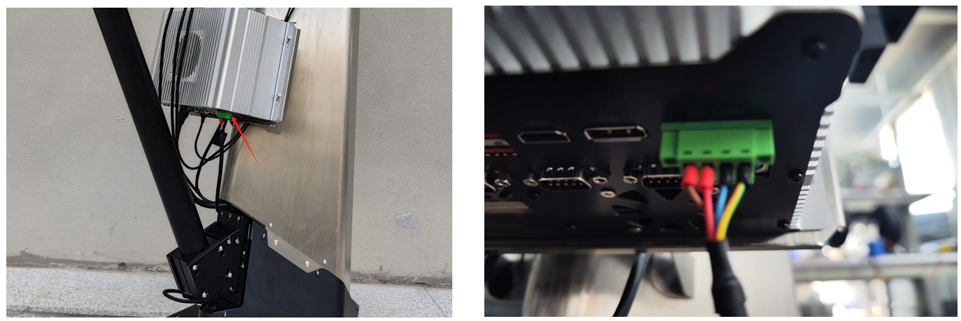
As shown in the upper left image, the power port of the industrial computer is located at the bottom of the unit. The green terminal needs to be plugged into the position indicated in the right image.
5.4 Screen Wiring
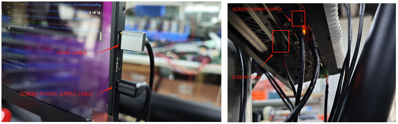
The HDMI port and TYPE-C power port of the screen are located on the right side of the screen, as shown in the left image. The HDMI cable and power cable need to be connected to the position shown in the right image.
5.5 Chassis Battery Wiring and Installation
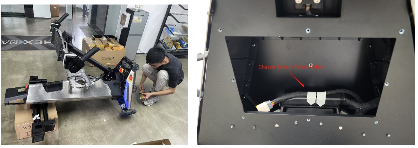
As shown in the figure above, lay the robot flat and use an appropriately sized object to prop up the front. This will reveal the battery compartment, as shown in the right image. The power cable, covered with masking tape, can be seen.

Next, remove the masking tape and connect this power cable to the battery's power cable.

The final step is to place the battery into the chassis battery compartment and tighten the eight securing screws.
5.6 Ethernet Port Wiring
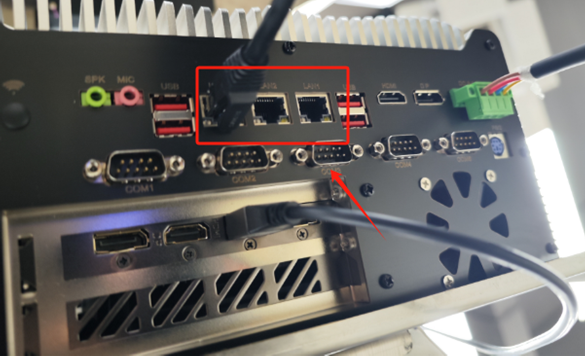
A router has already been installed inside the tower, and a network cable connected to the internal router is extended out. This network cable can be connected to any of the Ethernet ports indicated in the diagram.

There is an Ethernet port extended from the internal router located at the back of the industrial computer bracket, as shown in the two images above. This is a spare port used for debugging.
6. Robotic Arm Power Supply Instructions
6.1 Rear Platform Robotic Arm Power Cable
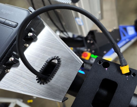
As shown in the above image, there is an XT30 power cable on each end of the rear platform, which is used to supply power to the teaching robotic arm on the rear platform.
6.2 Front Platform Robotic Arm Power Cable

As shown in the figure, each end of the front robotic arm installation platform has an XT30 power cable reserved for powering the robotic arm.
PoweringUp
1.Start Chassis
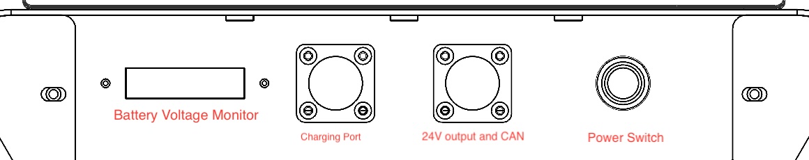
Turn the red rotary switch on the chassis to start the power of the entire machine. You will hear three beeps from the buzzer.The chassis can now be controlled with the remote, and power has been supplied to the robotic arm, lift mechanism, and computer.

2.Turn on Computer
If the computer does not start automatically, press the power button on the computer.

Start Developing
FIrst, make sure you have Ubuntu and ROS installed. Then please refer to https://docs.hexmove.cn/books/public-hexmove-docs/page/ros-sdk to install the SDK. Fibot SDK is in category Trigger.
CAN Protocol (Lifting Platform)
| Enable command | ||||
| Sender | Receiver | CAN ID | DLC | Period(ms) |
| Controller | Lifting Platform | 0x03020103 |
4 | / |
| data | function | data type | description | |
| byte[0] | / | uint8 | Fixed value 0x03 | |
| byte[1] | / | uint8 | Fixed value 0x02 | |
| byte[2] | / | uint8 | Fixed value 0x01 | |
| byte[3] | enable | uint8 | 0-disable 1-enable | |
| Heartbeat feedback | ||||
| Sender | Receiver | CAN ID | DLC | Period(ms) |
| Lifting Platform | Controller | 0x030201B0 |
1 | 500ms |
| data | function | data type | description | |
| byte[0] | enable | uint8 | 0-disable 1-enable | |
| Status command | ||||
| Sender | Receiver | CAN ID | DLC | Period(ms) |
| Controller | Lifting Platform | 0x03020111 |
3 | / |
| data | function | data type | description | |
| byte[0] | return to zero point | uint8 | 1-start | |
| byte[1] | max move velocity[0:7] | uint16 | unit: mm/s | |
| byte[2] | max move velocity[8:15] | |||
| Status feedback | ||||
| Sender | Receiver | CAN ID | DLC | Period(ms) |
| Lifting Platform | Controller | 0x030201B1 |
6 | 100ms |
| data | function | data type | description | |
| byte[0] | status | uint8 | 0:normal 1:abnormal | |
| byte[1] | return to zero point status | uint8 | 0-finished 1-calibrating | |
| byte[2] | errorcode [0:7] | uint16 | ||
| byte[3] | errorcode[8:15] | |||
| byte[4] | max move velocity [0:7] | uint16 | ||
| byte[5] | max move velocity[8:15] | |||
| Request move range command | ||||
| Sender | Receiver | CAN ID | DLC | Period(ms) |
| Controller | Lifting Platform | 0x03020112 |
0 | / |
| data | function | data type | description | |
| / | / | / | / | |
| Request move range feedback | ||||
| Sender | Receiver | CAN ID | DLC | Period(ms) |
| Lifting Platform | Controller | 0x030201B2 |
6 | / |
| data | function | data type | description | |
| byte[0] | move range[0:7] | uint16 | unit: mm | |
| byte[1] | move range[8:15] | |||
| byte[2]-byte[5] | reverse | uint8 | 0 | |
| Move velocity feedback | ||||
| Sender | Receiver | CAN ID | DLC | Period(ms) |
| Lifting Platform | Controller | 0x030201B3 |
6 | 50ms |
| data | function | data type | description | |
| byte[0] | velocity[0:7] | uint16 | unit: mm/s | |
| byte[1] | velocity[8:15] | |||
| byte[2]-byte[5] | reverse | uint8 | 0 | |
| Position setting command | ||||
| Sender | Receiver | CAN ID | DLC | Period(ms) |
| Controller | Lifting Platform | 0x03020114 |
6 | / |
| data | function | data type | description | |
| byte[0] | position[0:7] | uint16 | unit: mm | |
| byte[1] | position[8:15] | |||
| byte[2]-byte[5] | reverse | uint8 | 0 | |
| Move position feedback | ||||
| Sender | Receiver | CAN ID | DLC | Period(ms) |
| Lifting Platform | Controller | 0x030201B4 |
6 | 50ms |
| data | function | data type | description | |
| byte[0] | real position[0:7] | uint16 | unit: mm | |
| byte[1] | real position[8:15] | |||
| byte[2]-byte[5] | reverse | uint8 | 0 | |
Example
1. Enable device
CAN ID: 0x03020103, Data: 03 02 01 01
2. Set position 100mm
CAN ID: 0x03020114, Data: 64 00 00 00 00 00
CAN Protocol (Chassis)
| Reset | ||||
| Sender | Receiver | CAN ID | DLC | Period(ms) |
| Controller | Motor driver | 0x0505XX00 XX: driver id, can be 1 or 2 or 3 |
8 | / |
| data | function | data type | description | |
| byte[0] | / | uint8 | Fixed value 0x55 | |
| byte[1] | / | uint8 | Fixed value 0x55 | |
| byte[2] | / | uint8 | Fixed value 0x55 | |
| byte[3] | / | uint8 | Fixed value 0x55 | |
| byte[4] | / | uint8 | Fixed value 0x55 | |
| byte[5] | / | uint8 | Fixed value 0x55 | |
| byte[6] | / | uint8 | Fixed value 0x55 | |
| byte[7] | / | uint8 | Fixed value 0x55 | |
| Driver mode switch | ||||
| Sender | Receiver | CAN ID | DLC | Period(ms) |
| Controller | Motor driver | 0x0505XX01 XX: driver ID. Can be 1 or 2 or 3 |
8 | / |
| data | function | data type | description | |
| byte[0] | mode | uint8 | 2-open loop mode 3-velocity loop mode 4-position velocity loop mode 5-current loop mode 6-velocity current loop mode 7-position velocity current loop mode Note: typically the velocity current loop mode should be used. If you want to switch mode, you need to send reset first |
|
| byte[1] | / | uint8 | Fixed value 0x55 | |
| byte[2] | / | uint8 | Fixed value 0x55 | |
| byte[3] | / | uint8 | Fixed value 0x55 | |
| byte[4] | / | uint8 | Fixed value 0x55 | |
| byte[5] | / | uint8 | Fixed value 0x55 | |
| byte[6] | / | uint8 | Fixed value 0x55 | |
| byte[7] | / | uint8 | Fixed value 0x55 | |
| Open loop mode control | ||||
| Sender | Receiver | CAN ID | DLC | Period(ms) |
| Controller | Motor driver | 0x0505XX02 XX: driver ID. Can be 1 or 2 or 3 |
8 | 10ms |
| data | function | data type | description | |
| byte[0] | pwm_duty [15:8] | int16 | range [-3000,3000] | |
| byte[1] | pwm_duty [7:0] | |||
| byte[2] | / | uint8 | Fixed value 0x55 | |
| byte[3] | / | uint8 | Fixed value 0x55 | |
| byte[4] | / | uint8 | Fixed value 0x55 | |
| byte[5] | / | uint8 | Fixed value 0x55 | |
| byte[6] | / | uint8 | Fixed value 0x55 | |
| byte[7] | / | uint8 | Fixed value 0x55 | |
| Velocity mode control | ||||
| Sender | Receiver | CAN ID | DLC | Period(ms) |
| Controller | Motor driver | 0x0505XX03 XX: driver ID. Can be 1 or 2 or 3 |
8 | 10ms |
| data | function | data type | description | |
| byte[0] | pwm_duty [15:8] | int16 | range [-3000,3000] | |
| byte[1] | pwm_duty [7:0] | |||
| byte[2] | velocity [15:8] | int16 | unit: rpm, range [-500,500] | |
| byte[3] | velocity [7:0] | |||
| byte[4] | / | uint8 | Fixed value 0x55 | |
| byte[5] | / | uint8 | Fixed value 0x55 | |
| byte[6] | / | uint8 | Fixed value 0x55 | |
| byte[7] | / | uint8 | Fixed value 0x55 | |
| Position velocity mode control | ||||
| Sender | Receiver | CAN ID | DLC | Period(ms) |
| Controller | Motor driver | 0x0505XX04 XX: driver ID. Can be 1 or 2 or 3 |
8 | 10ms |
| data | function | data type | description | |
| byte[0] | pwm_duty [15:8] | int16 | range [-3000,3000] | |
| byte[1] | pwm_duty [8:0] | |||
| byte[2] | velocity [15:8] | int16 | unit: rpm, range [-500,500] | |
| byte[3] | velocity [8:0] | |||
| byte[4] | position[31:24] | int32 | range [-4096,4096] | |
| byte[5] | position[23:16] | |||
| byte[6] | position[15:8] | |||
| byte[7] | position[7:0] | |||
| Current loop mode control | ||||
| Sender | Receiver | CAN ID | DLC | Period(ms) |
| Controller | Motor driver | 0x0505XX05 XX: driver ID. Can be 1 or 2 or 3 |
8 | 10ms |
| data | function | data type | description | |
| byte[0] | current [15:8] | int16 | unit: 10mA, range [-7000,7000] | |
| byte[1] | current [7:0] | |||
| byte[2] | / | uint8 | Fixed value 0x55 | |
| byte[3] | / | uint8 | Fixed value 0x55 | |
| byte[4] | / | uint8 | Fixed value 0x55 | |
| byte[5] | / | uint8 | Fixed value 0x55 | |
| byte[6] | / | uint8 | Fixed value 0x55 | |
| byte[7] | / | uint8 | Fixed value 0x55 | |
| Velocity current mode control | ||||
| Sender | Receiver | CAN ID | DLC | Period(ms) |
| Controller | Motor driver | 0x0505XX06 XX: driver ID. Can be 1 or 2 or 3 |
8 | 10ms |
| data | function | data type | description | |
| byte[0] | current [15:8] | int16 | unit: 10mA, range [-7000,7000] | |
| byte[1] | current [7:0] | |||
| byte[2] | velocity [15:8] | int16 | unit: rpm, range [-500,500] | |
| byte[3] | velocity [7:0] | |||
| byte[4] | / | uint8 | Fixed value 0x55 | |
| byte[5] | / | uint8 | Fixed value 0x55 | |
| byte[6] | / | uint8 | Fixed value 0x55 | |
| byte[7] | / | uint8 | Fixed value 0x55 | |
| Position velocity current mode control | ||||
| Sender | Receiver | CAN ID | DLC | Period(ms) |
| Controller | Motor driver | 0x0505XX07 XX: driver ID. Can be 1 or 2 or 3 |
8 | 10ms |
| data | function | data type | description | |
| byte[0] | current [15:8] | int16 | unit: 10mA, range [-7000,7000] | |
| byte[1] | current [8:0] | |||
| byte[2] | velocity [15:8] | int16 | unit: rpm, range [-500,500] | |
| byte[3] | velocity [8:0] | |||
| byte[4] | position[31:24] | int32 | range [-4096,4096] | |
| byte[5] | position[23:16] | |||
| byte[6] | position[15:8] | |||
| byte[7] | position[7:0] | |||
| Set motor acceleration or deceleration | ||||
| Sender | Receiver | CAN ID | DLC | Period(ms) |
| Controller | Motor driver | 0x0505XX30 XX: driver ID. Can be 1 or 2 or 3 |
8 | / |
| data | function | data type | description | |
| byte[0] | open loop acc [15:8] | uint16 | if you set 1000,it means that the PWM duty cycle value takes 1 second to go from 0 to 1000 | |
| byte[1] | open loop acc [7:0] | |||
| byte[2] | open loop dec [15:8] | uint16 | if you set 1000,it means that the PWM duty cycle value takes 1 second to go from 1000 to 0 | |
| byte[3] | open loop dec [7:0] | |||
| byte[4] | velocity loop acc[15:8] | uint16 | if you set 100,it means that the rpm value takes 10 second to go from 0 rpm to 1000 rpm | |
| byte[5] | velocity loop acc [7:0] | |||
| byte[6] | velocity loop dec[15:8] | uint16 | if you set 100,it means that the rpm value takes 10 second to go from 1000 rpm to 0 rpm | |
| byte[7] | velocity loop dec [7:0] | |||
| set velocity loop(without current loop)PID param cmd | ||||
| Sender | Receiver | CAN ID | DLC | Period(ms) |
| Controller | Motor driver | 0x0505XX40 XX: driver ID. Can be 1 or 2 or 3 |
8 | The driver has default parameters that are sent when they need to be modified |
| data | function | data type | description | |
| byte[0] | P [31:24] | float | Proportion param | |
| byte[1] | P[23:16] | |||
| byte[2] | P[15:8] | |||
| byte[3] | P[7:0] | |||
| byte[4] | I [31:24] | float | Integral param | |
| byte[5] | I[23:16] | |||
| byte[6] | I[15:8] | |||
| byte[7] | I[7:0] | |||
| set position loop(without current loop)PID cmd | ||||
| Sender | Receiver | CAN ID | DLC | Period(ms) |
| Controller | Motor driver | 0x0505XX41 XX: driver ID. Can be 1 or 2 or 3 |
8 | The driver has default parameters that are sent when they need to be modified |
| data | function | data type | description | |
| byte[0] | P [31:24] | float | proportion param | |
| byte[1] | P[23:16] | |||
| byte[2] | P[15:8] | |||
| byte[3] | P[7:0] | |||
| byte[4] | D [31:24] | float | differential param | |
| byte[5] | D[23:16] | |||
| byte[6] | D[15:8] | |||
| byte[7] | D[7:0] | |||
| set current loop PID cmd | ||||
| Sender | Receiver | CAN ID | DLC | Period(ms) |
| Controller | Motor driver | 0x0505XX42 XX: driver ID. Can be 1 or 2 or 3 |
8 | The driver has default parameters that are sent when they need to be modified |
| data | function | data type | description | |
| byte[0] | P [31:24] | float | proportion param | |
| byte[1] | P[23:16] | |||
| byte[2] | P[15:8] | |||
| byte[3] | P[7:0] | |||
| byte[4] | I [31:24] | float | Integral param | |
| byte[5] | I[23:16] | |||
| byte[6] | I[15:8] | |||
| byte[7] | I[7:0] | |||
| set velocity loop(with current loop)PID cmd | ||||
| Sender | Receiver | CAN ID | DLC | Period(ms) |
| Controller | Motor driver | 0x0505XX43 XX: driver ID. Can be 1 or 2 or 3 |
8 | The driver has default parameters that are sent when they need to be modified |
| data | function | data type | description | |
| byte[0] | P [31:24] | float | proportion param | |
| byte[1] | P[23:16] | |||
| byte[2] | P[15:8] | |||
| byte[3] | P[7:0] | |||
| byte[4] | I [31:24] | float | Integral param | |
| byte[5] | I[23:16] | |||
| byte[6] | I[15:8] | |||
| byte[7] | I[7:0] | |||
| set position loop(with current loop)PID cmd | ||||
| Sender | Receiver | CAN ID | DLC | Period(ms) |
| Controller | Motor driver | 0x0505XX44 XX: driver ID. Can be 1 or 2 or 3 |
8 | The driver has default parameters that are sent when they need to be modified |
| data | function | data type | description | |
| byte[0] | P [31:24] | float | proportion param | |
| byte[1] | P[23:16] | |||
| byte[2] | P[15:8] | |||
| byte[3] | P[7:0] | |||
| byte[4] | D [31:24] | float | differential param | |
| byte[5] | D[23:16] | |||
| byte[6] | D[15:8] | |||
| byte[7] | D[7:0] | |||
| motor position velocity current feedback | ||||
| Sender | Receiver | CAN ID | DLC | Period(ms) |
| Motor driver | Controller | 0x0505XXB1 XX: driver ID. Can be 1 or 2 or 3 |
8 | 10ms |
| data | function | data type | description | |
| byte[0] | current [15:8] | int16 | unit: 10mA | |
| byte[1] | current [8:0] | |||
| byte[2] | velocity [15:8] | int16 | unit: rpm | |
| byte[3] | velocity [8:0] | |||
| byte[4] | position[31:24] | int32 | unit: qc | |
| byte[5] | position[23:16] | |||
| byte[6] | position[15:8] | |||
| byte[7] | position[7:0] | |||
| Driver status feedback | ||||
| Sender | Receiver | CAN ID | DLC | Period(ms) |
| Motor driver | Controller | 0x0505XXB2 XX: driver ID. Can be 1 or 2 or 3 |
8 | 100ms |
| data | function | data type | description | |
| byte[0] | pwm duty [15:8] | int16 | ||
| byte[1] | pwm duty [8:0] | |||
| byte[2] | voltage [15:8] | uint16 | unit: 0.01V | |
| byte[3] | voltage [8:0] | |||
| byte[4] | MOSFET temperature | uint8 | unit: ℃ | |
| byte[5] | motor temperature | uint8 | unit: ℃ | |
| byte[6] | error | uint8 | 0-normal 1-voltage over low 2-voltage over high 3-mosfet overtemperature 4-motor overtemperature 5-motor over current 6-encoder disconnect 7-encoder feedback direction is incorrect 8-encoder leads are not secure 9- hall sensor is abnormal |
|
| byte[7] | warning | uint8 | bit0-can watchdog timeout bit1-there is a gap in the Hall sensor |
|
| vcu error feedback | ||||
| Sender | Receiver | CAN ID | DLC | Period(ms) |
| VCU | Controller | 0x011101BA | 8 | 100ms |
| data | function | data type | description | |
| byte[0] | reverse | uint8 | 0 | |
| byte[1] | reverse | uint8 | 0 | |
| byte[2] | reverse | uint8 | 0 | |
| byte[3] | error | uint8 | bit0-Low battery warm bit1-Low battery error bit2-reverse bit3-emergency stop |
|
| byte[4] | reverse | uint8 | 0 | |
| byte[5] | reverse | uint8 | 0 | |
| byte[6] | reverse | uint8 | 0 | |
| byte[7] | reverse | uint8 | 0 | |
| VCU ctrl mode switch | ||||
| Sender | Receiver | CAN ID | DLC | Period(ms) |
| VCU | Controller | 0x01110111 | 8 | / |
| data | function | data type | description | |
| byte[0] | VCU mode | uint8 | 0-standby 1-reverse 2-VCU CAN mode 3-free mode 4-passthrough mode Note: After powering on, it is in passthrough mode by default |
|
| byte[1] | reverse | uint8 | 0 | |
| byte[2] | reverse | uint8 | 0 | |
| byte[3] | error | uint8 | 0 | |
| byte[4] | reverse | uint8 | 0 | |
| byte[5] | reverse | uint8 | 0 | |
| byte[6] | reverse | uint8 | 0 | |
| byte[7] | reverse | uint8 | 0 | |