Hardware Function
1. Handle Button Function Description
1.1 Tower handle
At the back of the tower, there is a handle button area, as shown in the figure below.
1.2 Rear platform handle
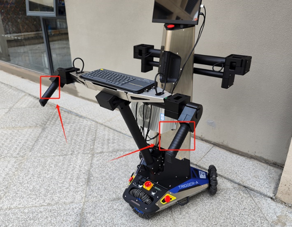
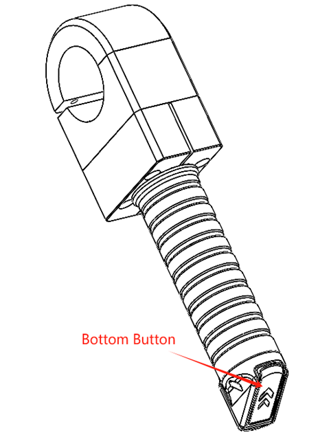
As shown in the left image above, the rear platform has two handles, each with two buttons. When the buttons on the back part of the handle, outlined in the red box in the left image, are pressed simultaneously, the chassis parking lock mode is released, allowing the chassis to be freely moved. In the right image above, there is another button below the handle, which is used to control the lifting. Pressing it will control the ascent or descent of the robotic arm platform in front
The two handles are not suitable for lifting the robot.
2. Rear Platform Keyboard Placement Instructions
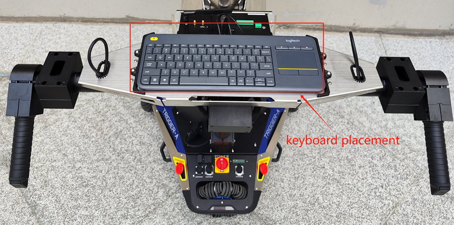
There are two black plastic components on the rear platform, designed to position the accompanying Logitech keyboard and prevent it from moving, as shown in the image.
3. Rear Platform Disassembly Instructions
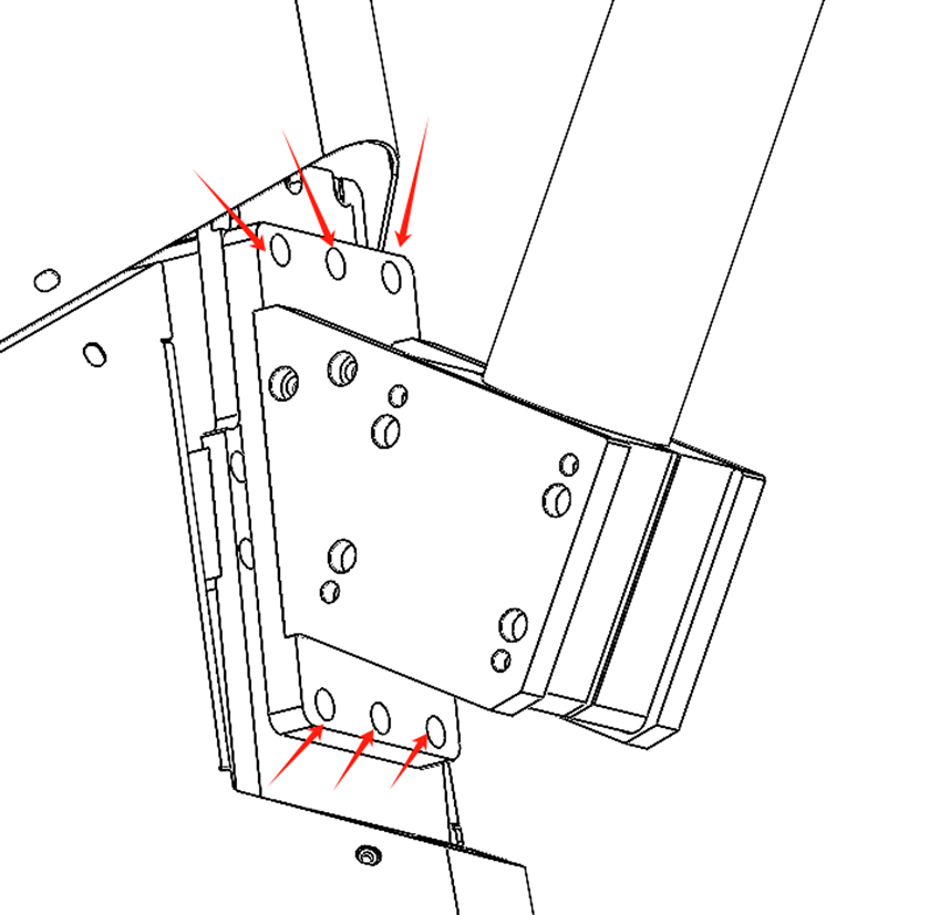
Considering that the robot may need to operate without the rear platform, the rear platform is designed to be removable. The specific removal method is shown in the image: unscrew the six screws indicated by the red arrows.
4. Robotic Arm Installation Instructions
4.1 Front Platform Robotic Arm Installation
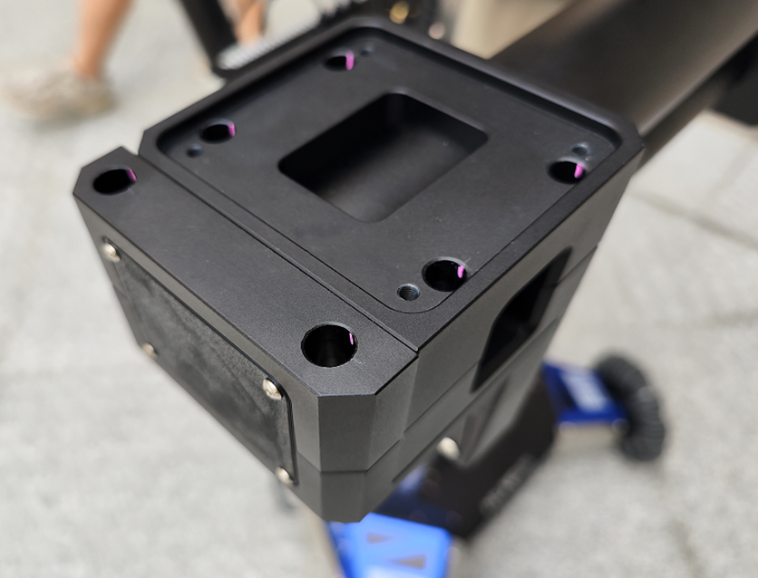
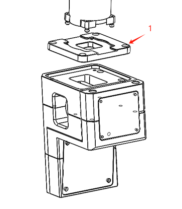
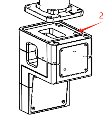
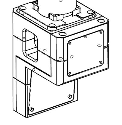
The robotic arm is mounted on the black machined part shown in the image above, and the specific installation process is illustrated as follows.
First, secure Part 1, as shown in the diagram, to the base of the robotic arm using screws. Then, attach Part 1 to Part 2 with screws as well.


