Prepare Hardware
1. Handle Button Function Description
1.1 Tower handle
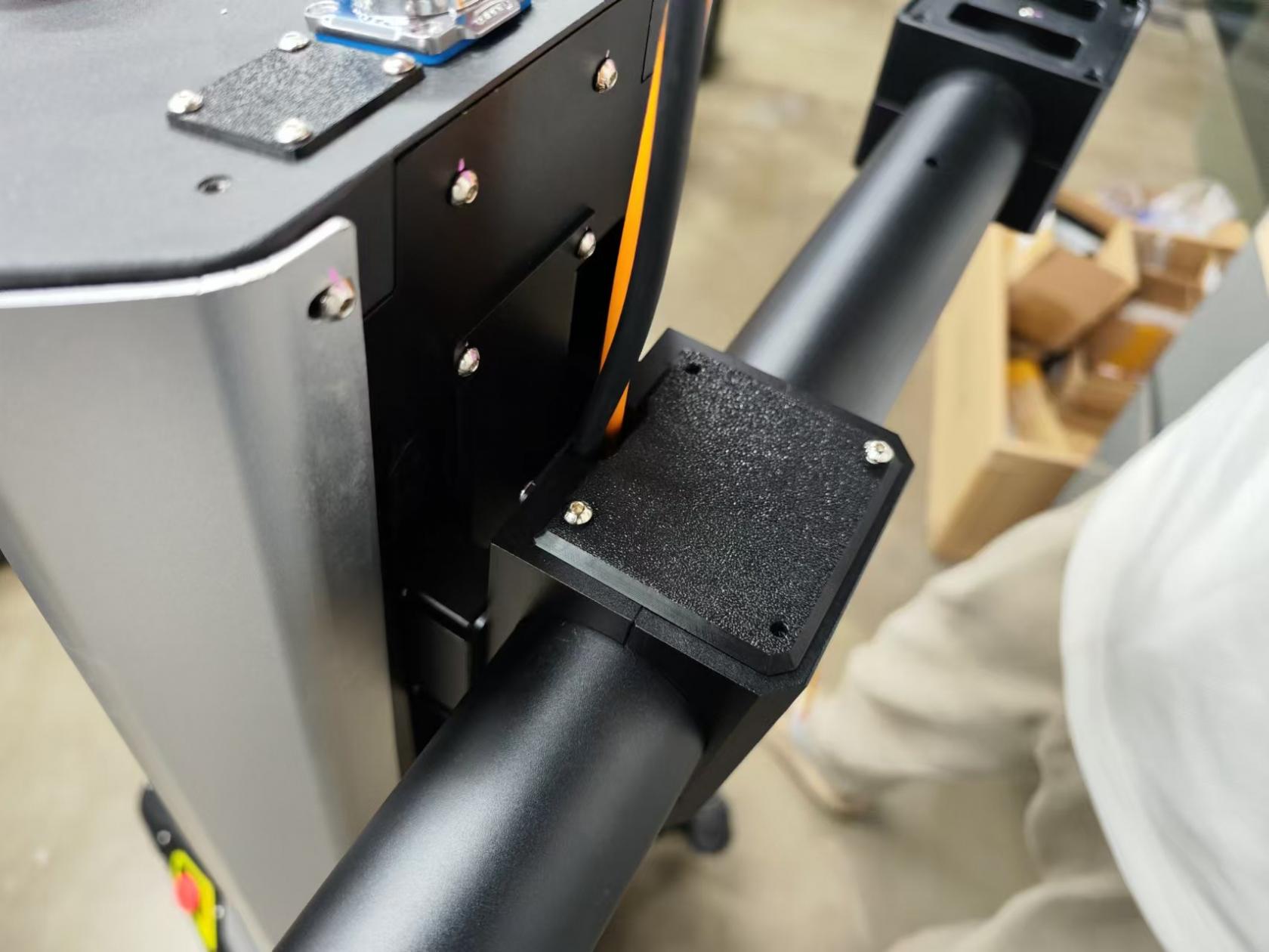
At the back of the tower, there is a handle button area, as shown in the figure below.
1.2 Rear platform handle
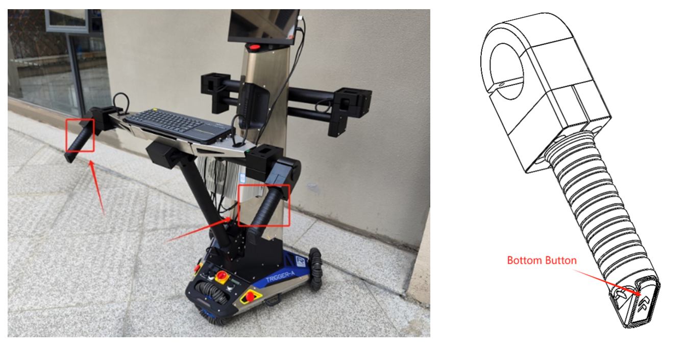
As shown in the left image above, the rear platform has two handles, each with two buttons. When the buttons on the back part of the handle, outlined in the red box in the left image, are pressed simultaneously, the chassis parking lock mode is released, allowing the chassis to be freely moved. In the right image above, there is another button below the handle, which is used to control the lifting. Pressing it will control the ascent or descent of the robotic arm platform in front
The two handles are not suitable for lifting the robot.
2. Rear Platform Keyboard Placement Instructions
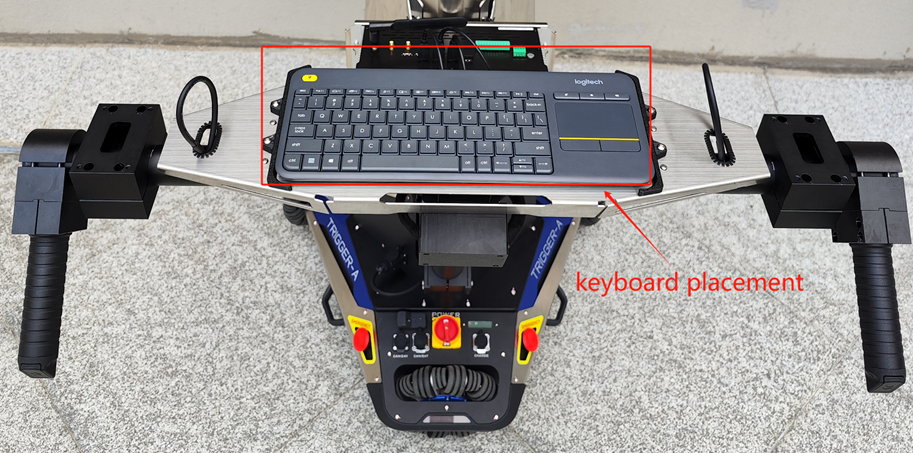
There are two black plastic components on the rear platform, designed to position the accompanying Logitech keyboard and prevent it from moving, as shown in the image.
3. Rear Platform Disassembly Instructions
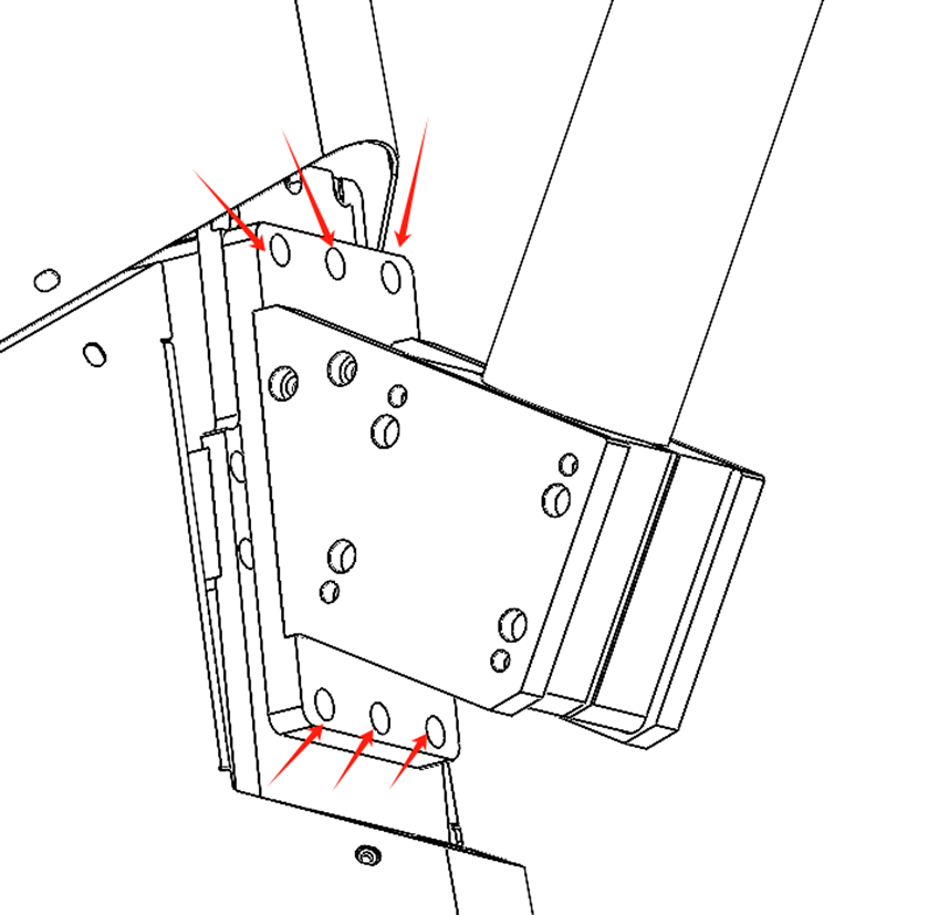
Considering that the robot may need to operate without the rear platform, the rear platform is designed to be removable. The specific removal method is shown in the image: unscrew the six screws indicated by the red arrows.
4. Front Paltform Installation Instructions
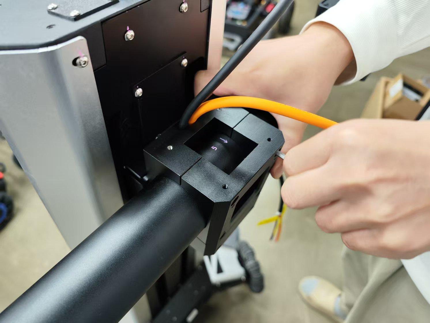
First of all, when installing the front platform, note that the pink arrow with the number 5 should face outward, consistent with the position in the image below.
In the second step, the parts fixing the aluminum tube are fixed by screws, as shown in the following figure.
Note that if installed according to the first step, the mounting plane of the mechanical arm is horizontal at this time, as shown in the following figure.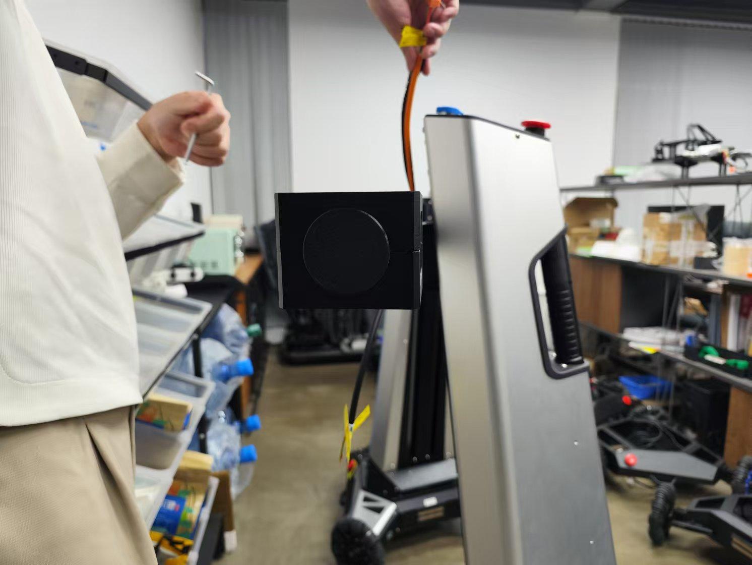
In the last step, the plastic parts of the cover plate are installed on the aluminum workpiece in the middle of the platform by screws, as shown in the following figure.
5. Wiring Instructions
5.1 Rear Platform Main Power Wiring
The rear platform has a black 4-pin aviation connector, which should be plugged into the socket located at the base of the tower, as shown in the image.
5.2 Three USB ports on the top of the tower
There are three USB 3.0 ports at the top of the tower, as shown in the left image, reserved for connecting cameras. The cables for these ports have already been extended to the base of the tower. You will need to connect the other end of these three USB ports to the industrial computer, as shown in the right image.
5.3 Industrial Computer Power Wiring
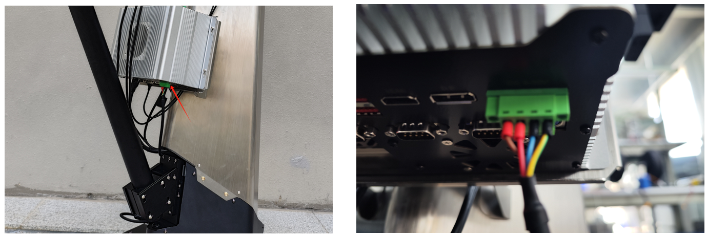
As shown in the upper left image, the power port of the industrial computer is located at the bottom of the unit. The green terminal needs to be plugged into the position indicated in the right image.
5.4 Screen Wiring
The HDMI port and TYPE-C power port of the screen are located on the right side of the screen, as shown in the left image. The HDMI cable and power cable need to be connected to the position shown in the right image.
5.5 Chassis Battery Wiring and Installation
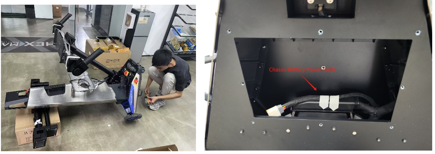
As shown in the figure above, lay the robot flat and use an appropriately sized object to prop up the front. This will reveal the battery compartment, as shown in the right image. The power cable, covered with masking tape, can be seen.
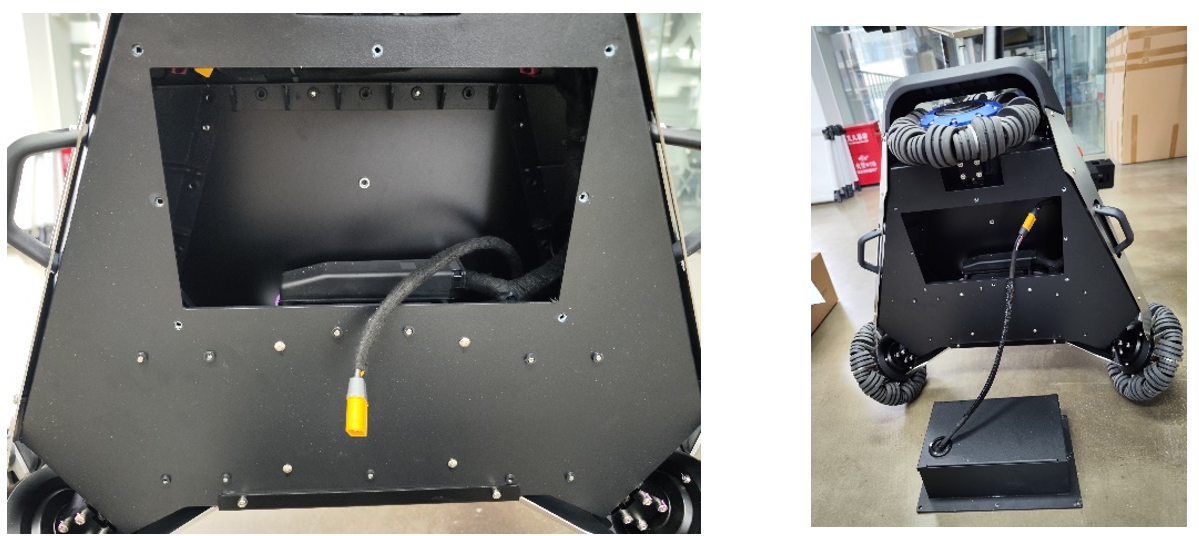
Next, remove the masking tape and connect this power cable to the battery's power cable.
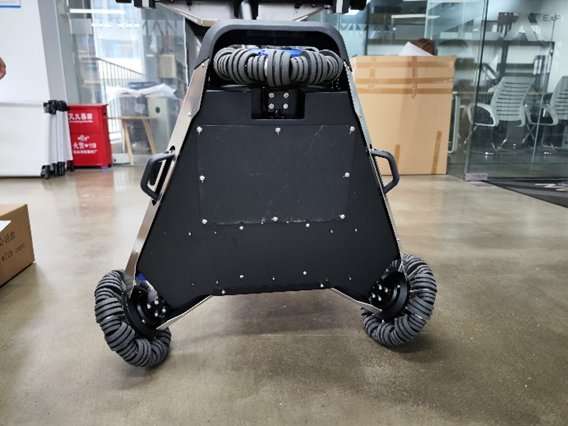
The final step is to place the battery into the chassis battery compartment and tighten the eight securing screws.
5.6 Ethernet Port Wiring
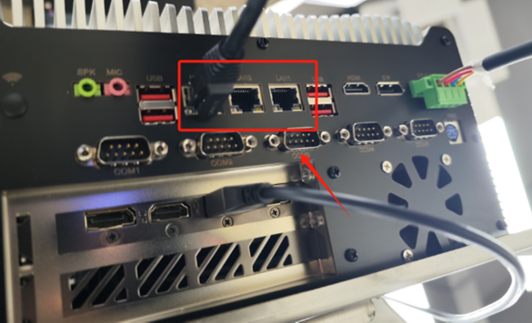
A router has already been installed inside the tower, and a network cable connected to the internal router is extended out. This network cable can be connected to any of the Ethernet ports indicated in the diagram.
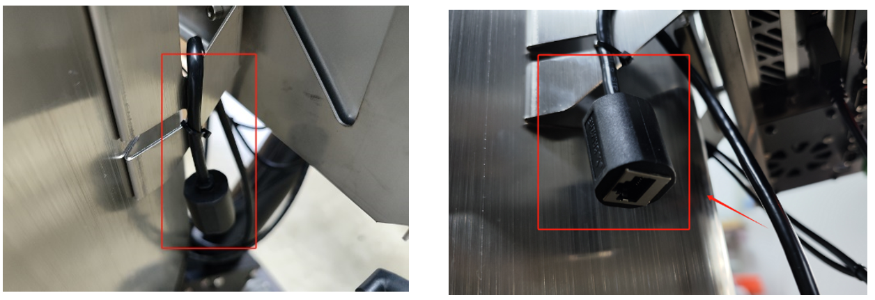
There is an Ethernet port extended from the internal router located at the back of the industrial computer bracket, as shown in the two images above. This is a spare port used for debugging.
6. Robotic Arm Power Supply Instructions
6.1 Rear Platform Robotic Arm Power Cable
As shown in the above image, there is an XT30 power cable on each end of the rear platform, which is used to supply power to the teaching robotic arm on the rear platform.
6.2 Front Platform Robotic Arm Power Cable
As shown in the figure, each end of the front robotic arm installation platform has an XT30 power cable reserved for powering the robotic arm.


